
Teach lesson
Arduino Visual Robot (4/4): marker-aware robot challenge
Students combine movement, sensors, markers, and reaction rules in a visual-programming robot challenge with documented test evidence.
Sign in with an educator account to prepare a class session. Students join with a class code.
New to LabsLand? Create your teacher account
Learning Outcomes
Use line sensors as evidence of light/dark surface reflectance.
Design a short reactive behaviour with input, decision, and output.
Evaluate a robot by evidence and explanation, not by perfect tracking.
Student activity preview
Activity Content
Preview only. In a class session, students can fill in responses and submit their work to the teacher.
Choose an achievable challenge
8 min
Black marks can be used as sensor evidence for a decision. The challenge is not precise line following; it is measuring light/dark surfaces and programming a reliable reaction.
The line sensors measure reflected light. Dark and light surfaces usually give different readings, but the actual ranges depend on the robot and its position. Measure both surfaces with the same sensor; do not assume a fixed value for white or black. A threshold is the number used to separate your observed readings.
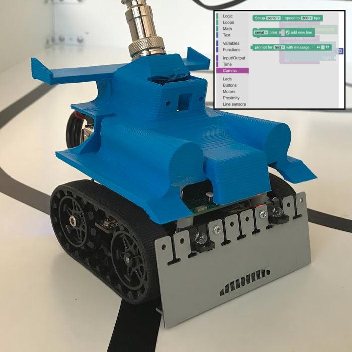
Build a surface traffic light: red for the dark line and blue for the light floor, with motors stopped during sensing. You will move between test positions only with the single-press positioning scaffold. A proximity-only program cannot answer this lesson’s line-sensor questions.
Write your chosen challenge as a rule: "If the sensor detects..., then the robot...; otherwise, the robot...".
Calibrate light and dark
18 min
Remote positioning: use the robot itself; you cannot move a physical object in the remote room. Select Only robots on 8-shaped circuits when uploading. Its white floor, black line and surrounding wall provide fixed references. First locate the robot’s front in the camera and check clear space. Add the button-controlled positioning scaffold below. Each new B press produces just one 100 ms forward pulse; release it before pressing again. A and C can use the same single-press pattern for left/right turns (−125,125 or 125,−125). Take a reading only after both motors stop. Never keep moving toward a wall to force a high reading; preserve a visible gap and report any positions you cannot safely sample.
[Button B as stepButton]  (Buttons)
[Setup Serial speed 9600]
Arduino run first:
  [Change two motors speed] Left: 0 Right: 0
Arduino loop forever:
  if [stepButton single press]:
    [Change two motors speed] Left: 125 Right: 125
    [wait] 100 milliseconds
    [Change two motors speed] Left: 0 Right: 0
  ... read sensors and show the value here ...
  [wait] 50 milliseconds
Use single press, not is pressed: it triggers once per new press, even if the button is held. Keep the separate Button B as stepButton configuration block in the workspace; select stepButton in the condition. The motor stop is inside the condition after the timed pulse. Test one press in clear space and watch for three seconds: it must remain stopped until a new press. If it does not move, do not lengthen the pulse blindly; check upload, button and available space.
After the positioning condition, use
Read line sensors, then print the center value and wait 300 ms. In the eight-shaped circuit, make short turns or forward pulses until the same center sensor is above the white floor; stop and record. Position it over the black line and record again. Check both surfaces on camera. If serial is unavailable, build the LED condition below first with trial threshold 500, then change it and retest both positions until the LED distinguishes them; record the tested threshold and LED state, not invented readings. If the surfaces cannot be distinguished, record low confidence and an inconclusive threshold.```text
[Read line sensors]
if [center line-sensor value >= your chosen number]: [Set red led to HIGH] [Set blue led to LOW]
else: [Set red led to LOW] [Set blue led to HIGH]
[Change two motors speed] Left: 0 Right: 0
```
| Sensor | Surface | Observed value (number or light/dark) | Proposed threshold | Confidence |
|---|---|---|---|---|
Give the threshold you tested and compare two table observations (serial readings or LED states at that threshold). If they do not separate light and dark, report an inconclusive calibration and a specific retest.
Retest and improve the rule
22 min
Now test whether the calibrated rule is repeatable. Return to the light surface and then the dark line, stopping before each reading. Predict each LED state before pressing a positioning button, then compare it with the result. If either result is inconsistent, change just the threshold, upload again and repeat both positions. Keep the motor-stop rule. Record the before/after result; an explained inconclusive calibration is valid evidence.
Describe one test that went well and one that should be improved. If you only ran one test, state what second test you would run.
Explain why your challenge does not depend on perfect line following. What concrete decision does the robot make from the sensor information?
Final submission
12 min
Final robot challenge
Submit:
- Challenge name.
- Main blocks used.
- Threshold and calibration evidence.
- Screenshot or description of the program.
- Observed result from the robot test.
- One concrete improvement.
What did you learn from programming a real robot that you would not learn from a simulation or from an Arduino board only?
Turn this preview into a live class session
Continue to LabsLand Teach to use this lesson with your students and review the access available to your account.
New to LabsLand? Create your teacher account